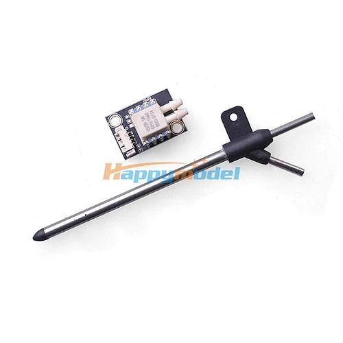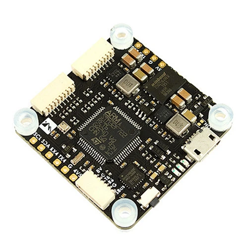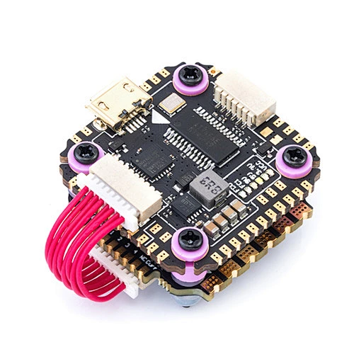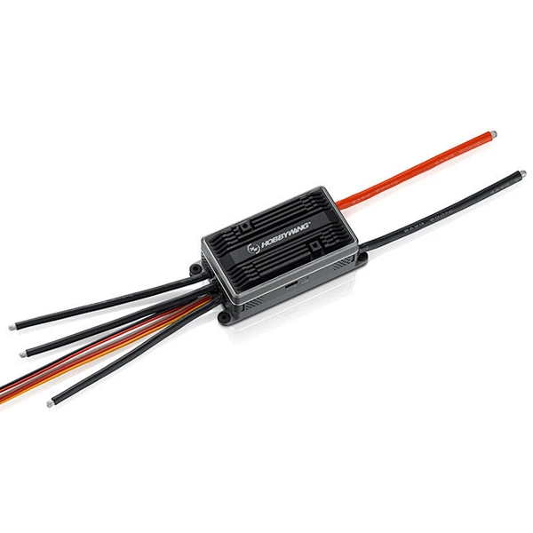








- Supported ESC type:490HZ or less PWM ESC
- Maximum output channel:8 channels
- website:www.lxrcmodel.com
- Gender:Unisex
- Age Range:14 Years & up
- Use:Vehicles & Remote Control Toys
- Place of Origin:CN;GUA
- Type:flight control
- Certification:other
- Brand Name:JIYI
- Model Number:XP664
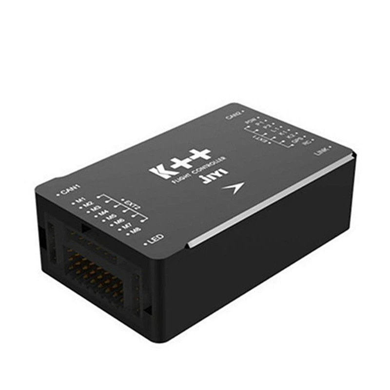
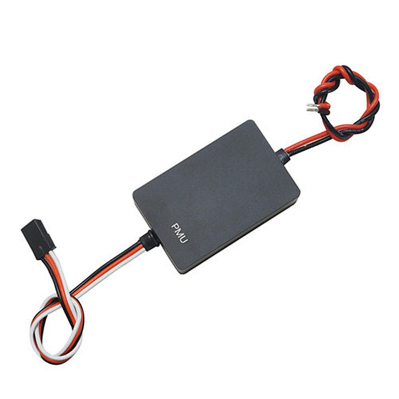
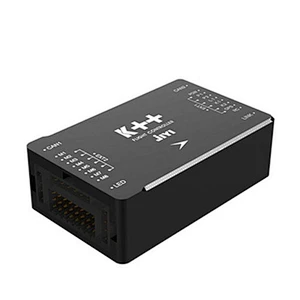
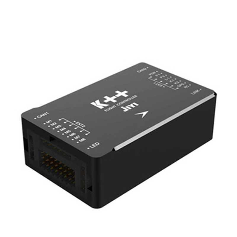
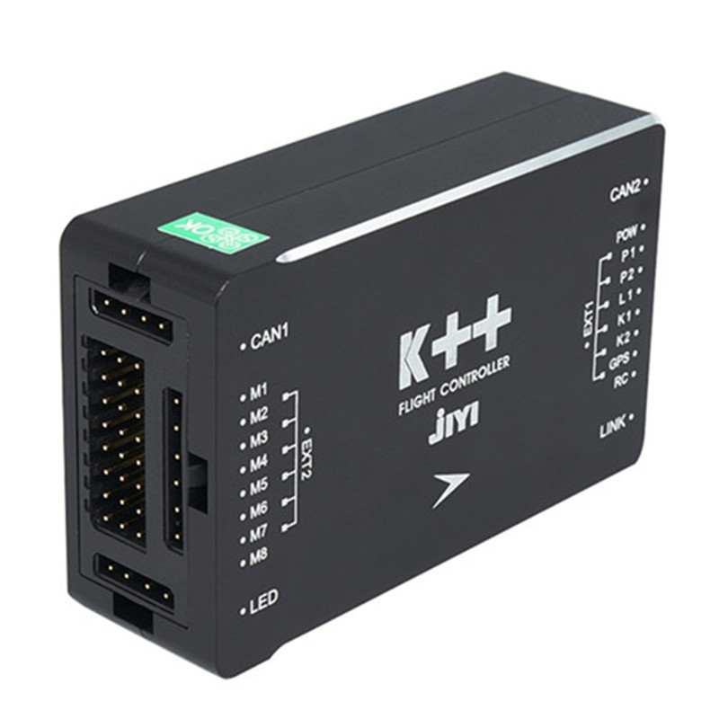
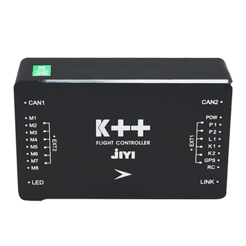
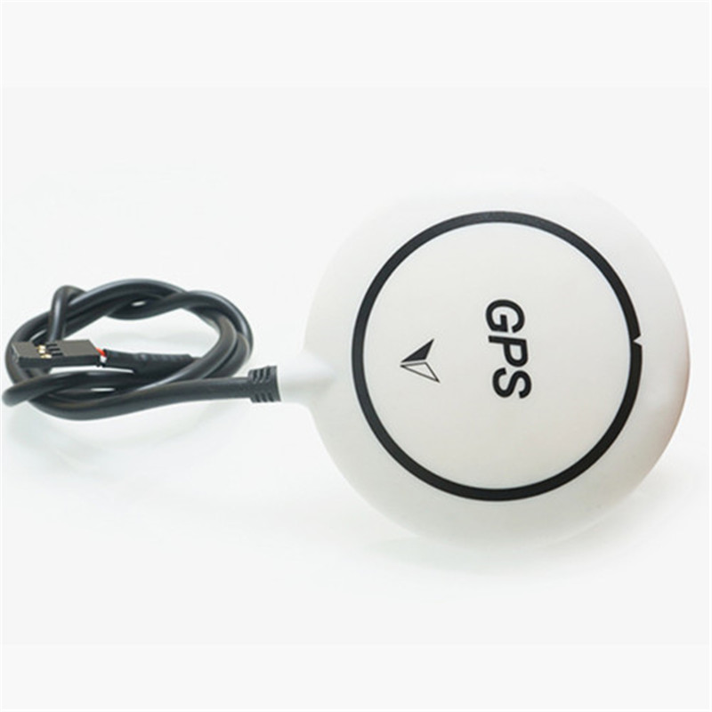
JIYI K++ Flight Controller with PMU / GPS Module for Agriculture Drones X4 I6 Y6 X8 I8 Multi-rotor
Features
Jiyi K ++ Flight Control Assistant Software is a software specially developed for K ++. Users can connect the flight controller and the computer’s USB port through a dedicated USB parameter adjustment cable. It provides flight control and aircraft related components (such as racks, remote controls, Expansion module, etc.) to view, set and upgrade flight control firmware, download flight logs, etc.
Intelligent vibration analysis function
K++ comes with intelligent vibration analysis function, which can determine the vibration of the aircraft in real time during flight, and display the safety warning in the APP to help adjust the adaptability of all aspects of the fuselage device, making the flight operation more energy efficient, safer and safer.
Multiple Backups
K++ is equipped with three redundant IMU and dual redundant barometer sensors. During the flight, the sensor data of IMU is monitored in real time through advanced diagnostic algorithms. When the sensor in the navigation system is abnormal, the system immediately switches to another sensor. To ensure the safe flight of the aircraft.
One calibration, not afraid of environmental interference
K++ benefits from powerful industrial-grade sensor configuration and algorithm optimization. After the same aircraft flight control system is installed, it only needs to be calibrated once. Even if the operating environment is replaced, it does not need to be recalibrated and is easy to use.
What is the Details of our Product?
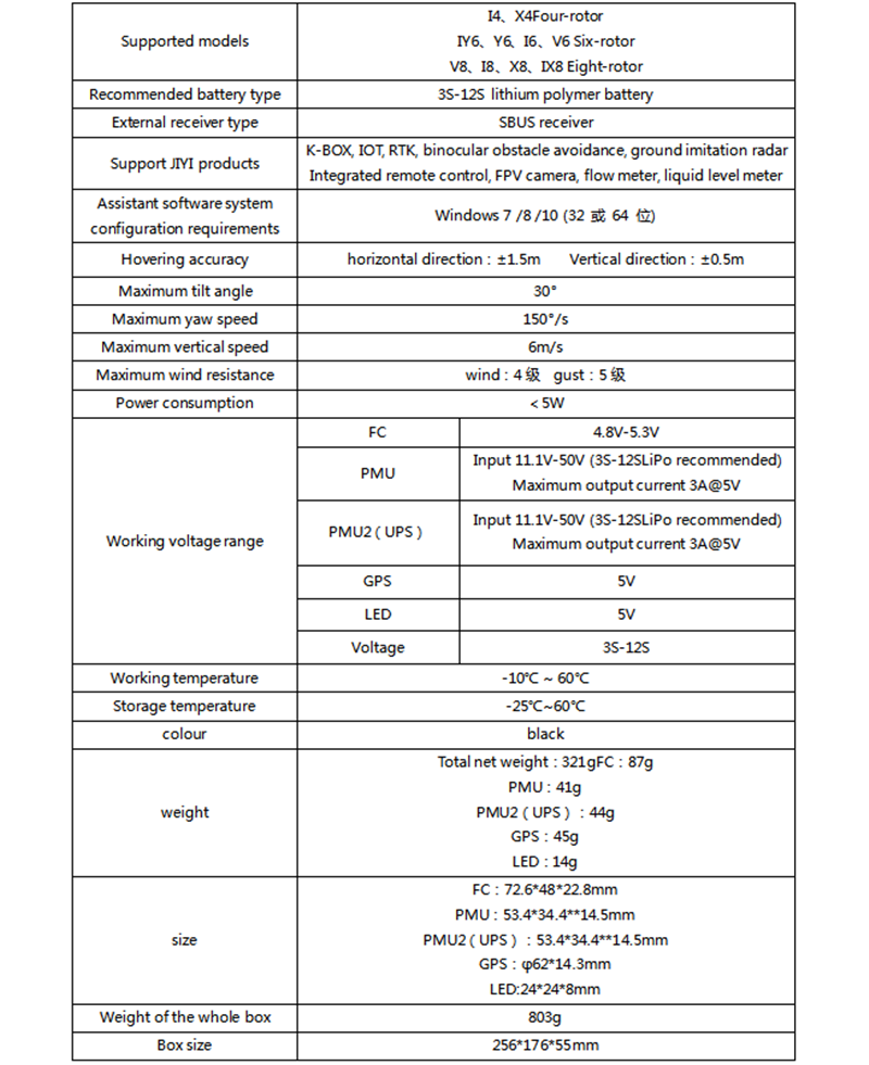
1. K ++ main control wiring diagram
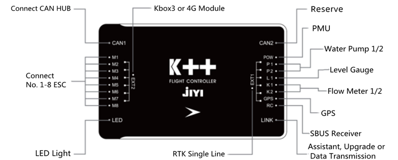
1). It needs to face up, not upside down, and try to keep it parallel to the fuselage;
2). In order to obtain the best flight effect, it is recommended to install the flight control level at the center of gravity of the aircraft. If the flight control installation position is not at the center of gravity of the aircraft, please fill in the corresponding installation distance in the Basic-> Installation-> Installation Position interface in the K ++ Assistant Software;
3). The flight controller has done a good job of internal shock absorption, and try to use hard 3M glue to fix the flight controller.
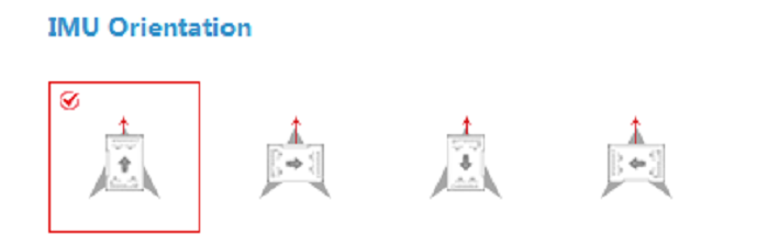
3. K ++ installation orientation requirements
As shown in the figure, select one of the installation directions, and select the corresponding configuration in the Basic-> Installation-> IMU Direction interface in the K++ Assistant Software. (The direction of the red arrow represents the head direction)
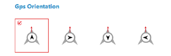
As shown in the figure, select one of the installation directions, and select the corresponding configuration in the Basic-> Installation-> GPS Direction interface in the K ++ Assistant Software. (The direction of the red arrow represents the head direction)
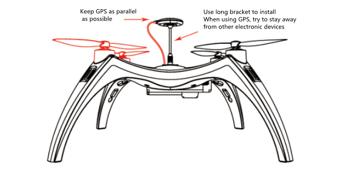
2). Try to ensure flight in an open and unobstructed environment;
3). Try to avoid flying in a magnetic interference environment;
4). Do not place strong magnetic substances near the compass, otherwise permanent damage to the compass may be caused.
Detailed Images
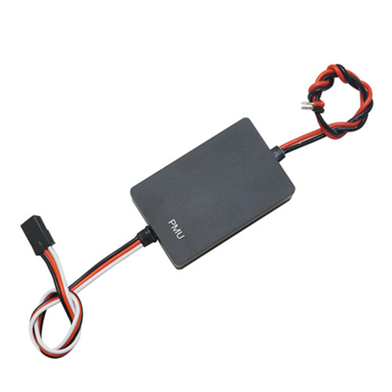
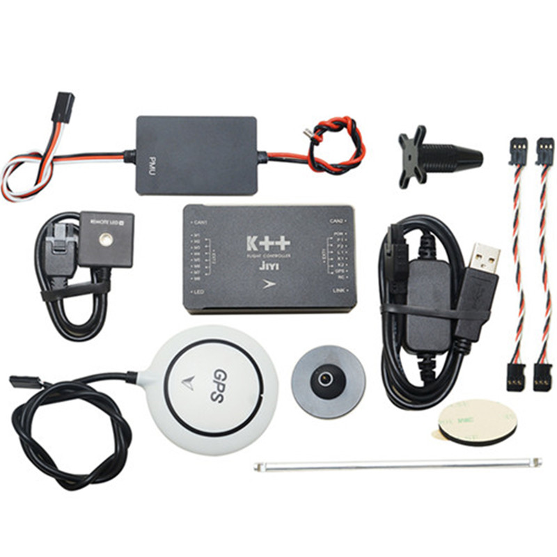
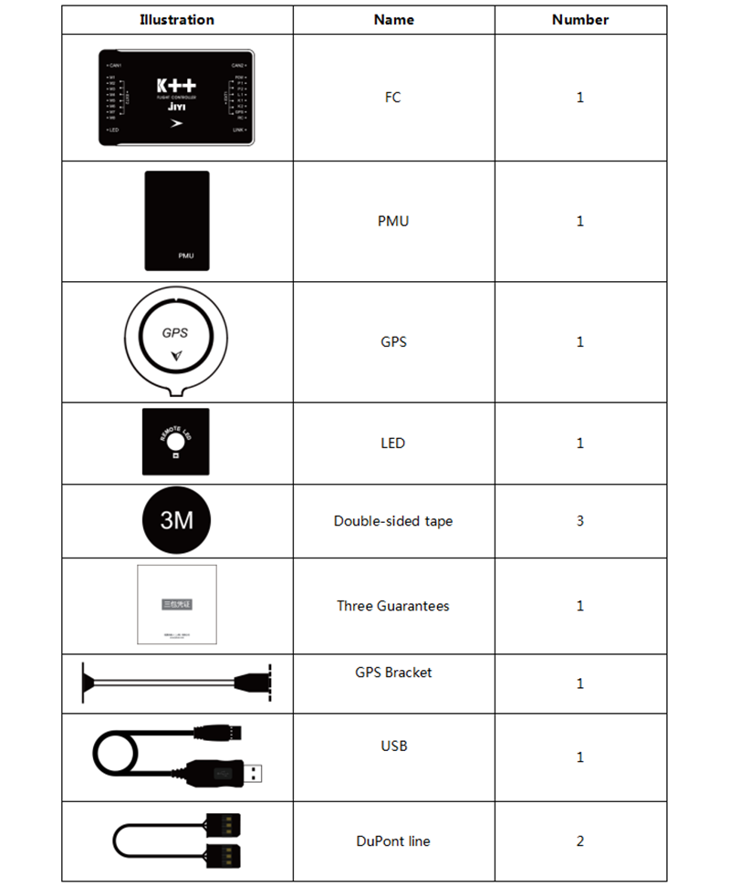
Item Packing